



Ever since our first fan made its way onto the ISS, other applications can easily appear mundane at first sight. Integrating a fan into a gaming mouse, for example, may seem comparatively “down to earth”. In fact, however, the g-forces that can act on a mouse when a passionate gamer goes “all in” are so high that this is a highly challenging environment for a fan to operate in. This is why we’ve custom-engineered two dedicated validation setups to safeguard that our NF-A4x10 fan is up to the task.

Movement patterns and acceleration force analysis
With gaming mice, there are two basic types of movement that can create acceleration forces which could potentially be problematic for fans: Horizontal in-plane movements along the x and y axis, where the mouse is moved sideways, forward or backward, and vertical or z-axis movements that occur when the mouse is lifted from the table and brought back down, hitting the table surface.
Both types of movement will pose severe stress on the fan’s bearing, but in different ways. While the horizontal in-plane movements introduce side-loads to the axis and bearing body, the vertical z-axis movements mainly load the bearing lock-ring as well as the wear disc underneath.
To ensure that our NF-A4x10 can withstand these loads, we first conducted an acceleration force analysis. We integrated an accelerometer into one of the mouse samples and measured the g-forces generated during intense mouse movements:

While the maximum acceleration forces we recorded were around 7 g, which correlates well with the consensus in the literature, values of up to 16 g were recorded when moving the mouse in the air as fast as possible. To account for absolute worst-case scenarios and to enable accelerated testing, we set a 20 g acceleration force level target when designing our validation setups.
Our validation setup for horizontal movement
Our validation setup for the horizontal in-plane movements utilises a boxer motor style scotch-yoke mechanism in order to apply repeated acceleration in a controlled and adjustable manner while maintaining mechanical balancing of the test apparatus.

The system consists of a scotch-yoke mechanism for translating rotation into sideways movement, gears and roller-pins, as well as an igus linear guiding system. It’s driven by an asynchronous motor with Variable Frequency Drive (VFD) and built into an aluminium extrusion profile frame.

- The centre-gear is driven by an asynchronous motor, which itself is driven by a variable frequency drive (VFD). The centre-gear is attached to the motor shaft using a centre-screw and three additional screws with a simple fixation plate.
- The side-gears are driven by the centre-gear, which itself is supported by dual-ball bearings and a compression ring on a CNC-machined axis in a CNC-machined base plate. The ball bearings and the side-gear are secured using regular retaining clips (DIN 471).
- Roller-pins are screwed into the side-gears, at a radius of 25mm. The roller-pin position was carefully drilled to be aligned with a centre of a tooth, to ensure as good as possible mechanical synchronisation and thus balancing. Similarly, the number of teeth for the centre-gear and side-gears was chosen to be even, also due to mechanical synchronisation and balancing reasons.
- Sledge-plates with a slotted hole are driven by the roller-pins, thus forming a scotch-yoke mechanism (translating rotational movement into translational movement).
- The sledge-plates are screwed onto an igus linear guiding carriage, which itself moves along an igus linear guide.

To ensure mechanical safety, both ends of the linear guides use 5 mm thick aluminium plates as limit stops, which prevent that the entire sledge assembly from shooting out of the apparatus in case the roller-pins fail. Finally, a 2 mm aluminium bent sheet metal protective cover is screwed on to lower the risk of unintended contact with moving components.

To make sure that the apparatus will provide the target peak acceleration force of 20 g, we calculated the translational acceleration as a function of the rotational movement to determine the required motor RPM speed.

The calculated target RPM speed of 1410 RPM (different from the initial handwritten calculation draft that still had 50/55 mm instead of 25 mm radius) was then validated using an accelerometer, confirming that the test setup produces the intended 20 g acceleration force. This video demonstrates how the setup looks and sounds operating at 30 Hz (30 sideways movements per second), producing around 7.5 g of translational acceleration:
Your consent is required to load YouTube videos.
YouTube (Google) stores cookies and collects data with embedded videos. By activating videos on our website, you agree to YouTube's data policy.
Drop test validation setup
To replicate the vertical movement that can occur when gamers smash their mice down against the table, we have designed a drop test apparatus that utilises a toothed rack and gearwheel with a freewheel section:

In this setup, a DC motor drives the gearwheel that is pulling up the toothed rack and the attached drop carriage along igus linear guiding rods. Once the freewheel section of the gearwheel is reached, the toothed rack and drop carriage will drop down onto the 3D-printed base. The freewheel section was designed large enough to give sufficient time for dropping the total height of 20 cm.

Foam was added at the base to soften the impact between the screw heads at the drop carriage and the bottom base, as well as to reduce acoustical noise. Again, we validated the setup using an accelerometer to make sure that the target acceleration force of 20 g is reached with sufficient foam padding. The following video shows the setup performing the repeated drop tests at 20 g:
Your consent is required to load YouTube videos.
YouTube (Google) stores cookies and collects data with embedded videos. By activating videos on our website, you agree to YouTube's data policy.
Test results: How long can a fan survive this type of torture?
The answer to the question of how long NF-A4x10 fans can survive this type of torture is simple: surprisingly long! In particular, the fans proved to be remarkably resilient against the in-plane horizontal movement, even though it introduces severe sideways loading onto the bearing body and axis.
When we stopped the horizontal test after 280.000 cycles because one out of twelve fans failed, it was due to a broken cable rather than a bearing issue! The tape that we used to fix the fan’s cable to the dedicated cable support had become loose, which caused the cable to bend during movement, and this repeated bending eventually led to failure. The other eleven fans were still going strong, and once we fixed the broken cable, the twelfth didn’t show any sign of weakness either!
In the vertical drop test, eight out of eight fans survived 20.000 drops without any issues. After another 5000 drops, all the fans had their impellers pop out due to failures of the bearing lock-ring, but by this time, the foam padding at the base of the test setup that we used to soften the impact was completely shattered, so the impact force had become much higher than our accelerometer could measure – without padding, the acceleration force was likely several dozen g’s!

Conclusion: Ready to go!
When analysing the test results, it quickly became clear that our initial concern whether the NF-A4x10 would be able to withstand the acceleration forces that can occur inside a gaming mouse was unfounded.
Thanks to our custom-built validation setups, we can now confidently say that the fans can not only tolerate acceleration forces that go way beyond what can happen even in the most extreme gaming situations, but they can also withstand these forces for a number of repetitions that even the most avid gamers are unlikely to reach within a decade.
Mentioned products
Explore the products featured in this article.

Pulsar Feinmann F01 Noctua Edition
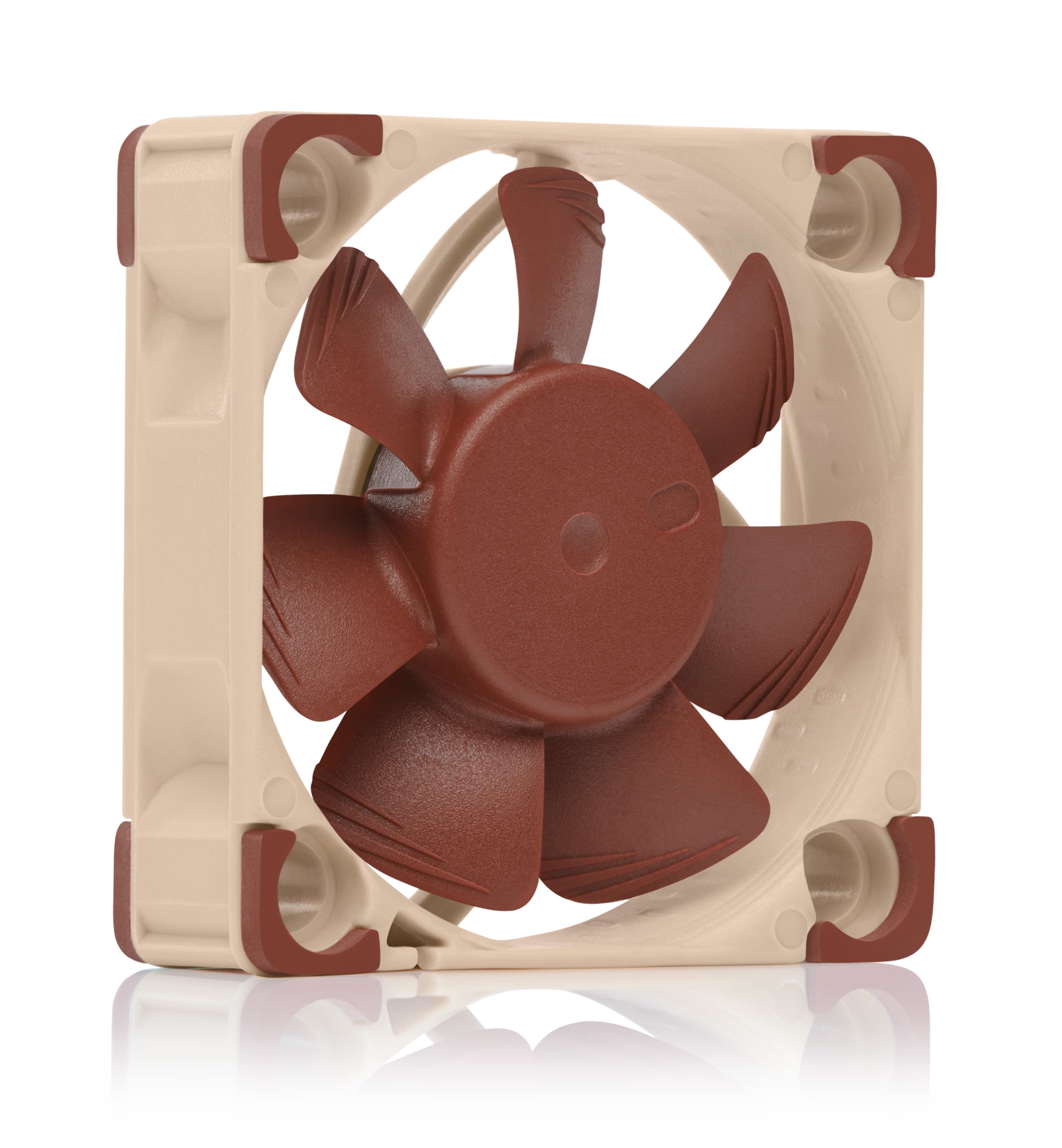
NF-A4x10 5V PWM
Related articles
Want to learn more? Explore related articles and resources.
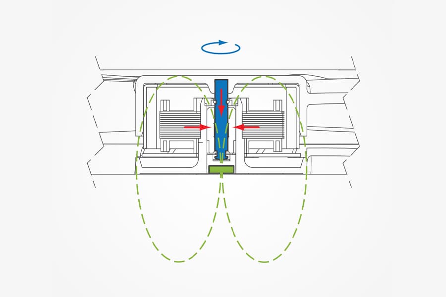
SSO2 bearing
The second-generation 'SSO2' bearing combines hydrodynamic stabilisation with a rear magnet for ultimate precision, quietness, and durability.
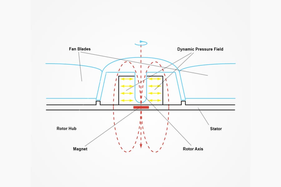
SSO bearing
Noctua’s SSO bearing uses dynamic oil pressure and a stabilising magnet for quiet, long-lasting performance.
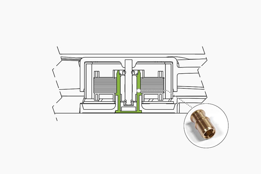
Metal bearing shell
Many of Noctua's models sport a CNC milled bearing shell made entirely from brass.